Difference between revisions of "Howto Fortigate"
| (6 intermediate revisions by the same user not shown) | |||
| Line 167: | Line 167: | ||
When finished click OK. | When finished click OK. | ||
| − | [[File:Fortigate- | + | [[File:Fortigate-pic-5a.jpg]] |
=== Phase 2 Parameters === | === Phase 2 Parameters === | ||
| Line 203: | Line 203: | ||
When finished click OK. | When finished click OK. | ||
| − | [[File:Fortigate- | + | [[File:Fortigate-pic-5b.jpg]] |
=== Firewall Policies === | === Firewall Policies === | ||
| Line 209: | Line 209: | ||
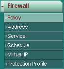
Firewall policies must be created to define the resources remote access clients will have access to. Navigate to the following screen using the pane on the left hand side of the browser interface. | Firewall policies must be created to define the resources remote access clients will have access to. Navigate to the following screen using the pane on the left hand side of the browser interface. | ||
| − | [[ | + | [[File:Fortigate-nav-6a.jpg]] |
To create a new policy, click the ''Create New'' button at the top of the screen. | To create a new policy, click the ''Create New'' button at the top of the screen. | ||
| − | [[ | + | [[File:Fortigate-nav-6b.jpg]] |
The first policy will allow clients to communicate with the external interface DHCP server. | The first policy will allow clients to communicate with the external interface DHCP server. | ||
| Line 237: | Line 237: | ||
When finished click OK. | When finished click OK. | ||
| − | [[ | + | [[File:Fortigate-pic-6a.jpg]] |
The second policy will allow clients to communicate with the private network protected by the Fortigate. A seperate policy needs to be created for each private network that should be accessible to remote access clients. | The second policy will allow clients to communicate with the private network protected by the Fortigate. A seperate policy needs to be created for each private network that should be accessible to remote access clients. | ||
| Line 261: | Line 261: | ||
When finished click OK. | When finished click OK. | ||
| − | [[ | + | [[File:Fortigate-pic-6b.jpg]] |
== Client Configuration == | == Client Configuration == | ||
| Line 301: | Line 301: | ||
== Resources == | == Resources == | ||
| − | [ | + | [[Media:fortigate.vpn.txt]] |
Latest revision as of 05:03, 9 January 2013
Contents
Introduction
This guide provides information that can be used to configure a Fortigate device to support IPsec VPN client connectivity. The Shrew Soft VPN Client has been tested with Fortigate products to ensure interoperability.
Overview
The configuration example described below will allow an IPsec VPN client to communicate with a single remote private network. The client uses the DHCP over IPsec configuration method to acquire the following parameters automatically from the gateway.
- IP Address
- IP Netmask
- DNS Servers
- DNS Default Domain Suffix
- WINS Servers
Gateway Configuration
This example assumes you have knowledge of the Fortigate web configuration interface. For more information, please consult your Fortigate product documentation.
Interfaces
Two network interfaces are configured. The wan interface has a static public IP address of 10.1.1.22 which faces the internet. The internal interface has a static private IP address of 10.1.2.22 which faces the internal private network. The default gateway is configured as 1.1.1.1 via the WAN interface.
Address Definitions
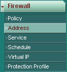
Several address definitions must be created. These will be used later in other parts of the gateway configuration. Navigate to the following screen using the pane on the left hand side of the browser interface.
To create a new address definition, click on the Create New button at the top of the page.
Wan Interface Entry
Create an address definition to represent the IP address of the public interface. This will be used later in a firewall policy definition to allow clients to communicate with the DHCP server via IPsec.
Define the following parameters.
- Address Name = gateway_wan1
- Type = Subnet / IP Range
- Subnet / IP Range = 10.1.1.22/255.255.255.255
- Interface = wan1 [ or your external interface ]
When finished click OK.
Private Network Entry
Create an address definition to represent the private network protected by the Fortigate. This will be used later in a firewall policy definition to allow clients to communicate with the private network via IPsec.
Define the following parameters.
- Address Name = gateway_prvnet1
- Type = Subnet / IP Range
- Subnet / IP Range = 10.1.2.0/255.255.255.0
- Interface = internal [ or your internal interface ]
When finished click OK.
DHCP Server Parameters
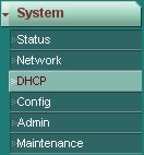
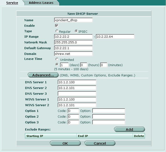
An IPsec over DHCP server must be created. This will define the parameters to be assigned to clients when they connect. Navigate to the following screen using the pane on the left hand side of the browser interface.
To create a new DHCP server definition, click on the arrow next to your external interface name to expand the options. Then click on the plus icon to the right of the Servers option.
When defining your DHCP parameters, make sure you select an address range that does not overlap with any private network protected by the Fortigate unit.
Define the following parameters.
- Name = vpnclient_dhcp
- Enable = Checked
- Type = IPSEC
- IP Range = 10.2.22.2 - 10.2.22.64 [ or your desired range ]
- Network Mask = 255.255.255.0
- Default Gateway = 10.2.22.1
- Domain = yourdomain.com
- Lease Time = 1 day
Dialup Users
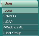
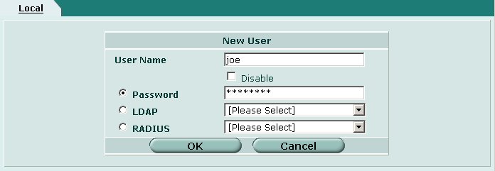
Dialup user accounts must be created. These will be the user name and passwords a remote access users will use to authenticate with the gateway. Navigate to the following screen using the pane on the left hand side of the browser interface.
To create a new user, click on the Create New button at the top of the page.
Define the following parameters for each user account.
- User Name = User account name
- Password = User account password
When finished click OK.
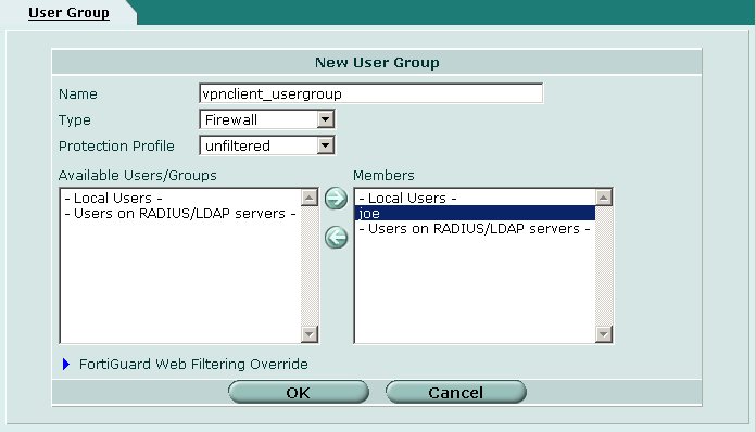
Dialup User Group
A dialup user group must be created. By placing a user account in this group, it will allow them to access the gateway using the client software. Navigate to the following screen using the pane on the left hand side of the browser interface.
To create a new user group, click on the Create New button at the top of the page.
Define the following parameters for each user account.
- Name = vpnclient_usergroup
- Type = Firewall
- Protection Profile = unfiltered
Next, select the remote access user account names from the left hand Available list and add them to the right hand Members list.
When finished click OK.
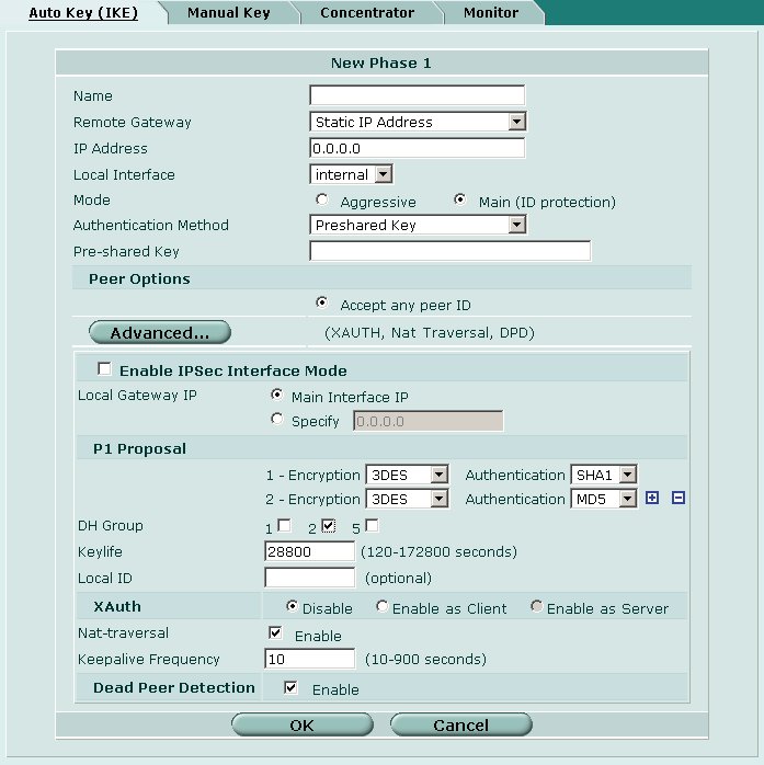
Phase 1 Parameters
The IKE phase 1 parameters must be configured for our remote access connections. Navigate to the following screen using the pane on the left hand side of the browser interface.
To create a new Phase 1 definition, click on the Create Phase 1 button at the top of the screen.
Define the following parameters.
- Name = vpnclient_phase1
- Remote Gateway = Dialup User
- Local Interface = wan1 [ or your external interface ]
- Mode = Aggressive
- Authentication Method = Preshared Key
- Preshared Key = mypresharedkey
- Peer Options
- Accept this peer ID = vpnclient.yourdomain.com
Advanced
- Local Gateway IP = Main Interface IP
- P1 Proposal
- 1 - Encryption / Authentication = 3DES / MD5
- 2 - Encryption / Authentication = AES256 / MD5
- DH Group = 2
- Keylife = 28800 seconds
- Local ID = [ blank ]
- XAuth = Enable as Server
- Server Type = AUTO
- User Group = vpnclient_usergroup
- Nat Traversal = Checked
- Keepalive Frequency = 10 seconds
- Dead Peer Detection = Checked
When finished click OK.
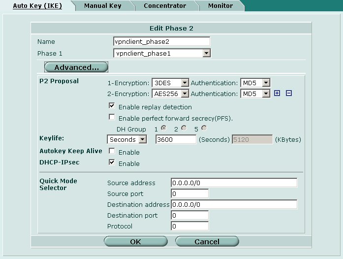
Phase 2 Parameters
The IKE phase 2 parameters must be configured for our remote access connections. Navigate to the following screen using the pane on the left hand side of the browser interface.
To create a new Phase 2 definition, click on the Create Phase 1 button at the top of the screen.
Define the following parameters.
- Name = vpnclient_phase2
- Phase 1 = vpnclient_phase1
Advanced
- P2 Proposal
- 1 - Encryption / Authentication = 3DES / MD5
- 2 - Encryption / Authentication = AES256 / MD5
- Enable replay detection = Checked
- Enable perfect forward secrecy = Unchecked
- Keylife = 3600 seconds
- Autokey Keep Alive = Unchecked
- DHCP-IPsec = Checked
- Quick Mode Selector
- Source address = 0.0.0.0/0
- Source port = 0
- Destination address = 0.0.0.0/0
- Destination port = 0
- Destination protocol = 0
When finished click OK.
Firewall Policies
Firewall policies must be created to define the resources remote access clients will have access to. Navigate to the following screen using the pane on the left hand side of the browser interface.
To create a new policy, click the Create New button at the top of the screen.
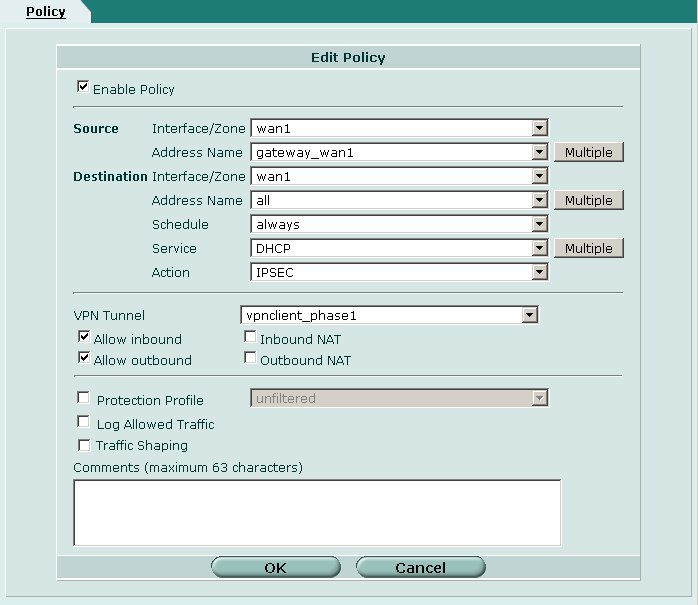
The first policy will allow clients to communicate with the external interface DHCP server.
Define the following parameters.
- Enable Policy = Checked
- Source
- Interface / Zone = wan1 [ or your external interface ]
- Address Name = gateway_wan1
- Destination
- Interface / Zone = wan1 [ or your external interface ]
- Address Name = all
- Schedule = always
- Service = DHCP
- Action = IPSEC
- VPN Tunnel = vpnclient_phase1
- Allow Inbound = Checked
- Allow Outbound = Checked
- Inbound NAT = Unchecked
- Outbound NAT = Unchecked
When finished click OK.
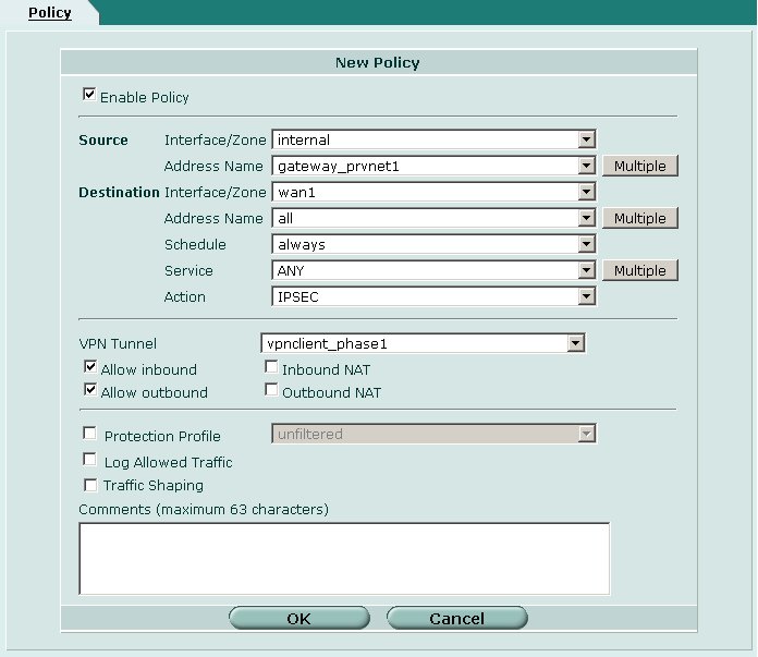
The second policy will allow clients to communicate with the private network protected by the Fortigate. A seperate policy needs to be created for each private network that should be accessible to remote access clients.
Define the following parameters.
- Enable Policy = Checked
- Source
- Interface / Zone = internal [ or your internal interface ]
- Address Name = gateway_prvnet1
- Destination
- Interface / Zone = wan1 [ or your external interface ]
- Address Name = all
- Schedule = always
- Service = ANY
- Action = IPSEC
- VPN Tunnel = vpnclient_phase1
- Allow Inbound = Checked
- Allow Outbound = Checked
- Inbound NAT = Unchecked
- Outbound NAT = Unchecked
When finished click OK.
Client Configuration
The client configuration in this example is straight forward. Open the Access Manager application and create a new site configuration. Configure the settings listed below in the following tabs.
General Tab
The Remote Host section must be configured. This Host Name or IP Address is defined as 10.1.2.22 to match the Fortigate wan interface address. The Auto Configuration option is set to dhcp over ipsec.
Phase 1 Tab
The Proposal section must be configured to match the Fortigate Phase 1 definition. The Exchange Type is set to aggressive and the DH Exchange is set to group 2.
Authentication Tab
The client authentication settings must be configured. The Authentication Method is defined as Mutual PSK + XAuth.
Local Identity Tab
The Local Identity parameters are defined as Fully Qualified Domain Name with a FQDN String of "vpnclient.domain.com" to match the Fortigate Phase 1 definition.
Remote Identity Tab
The Remote Identity parameters are set to IP Address with the Use a discovered remote host address option checked to match the Zywall Gateway Policy definition.
Credentials Tab
The Credentials Pre Shared Key is defined as "mypresharedkey" to match the match the Zywall Gateway Policy definition.
Policy Tab
The IPsec Policy configuration must be manually configured when communicating with Fortigate gateways. A single Topology Entry is defined to include the 10.1.2.0/24 network.
Known Issues
There is a known issue with Fortigate firmware revision 3.00-b0660(MR6). The problem prevents Xauth ( user authentication ) from working with peers that correctly implement the RFC draft. To correct this issue, upgrade your Fortigate unit to firmware revision 3.00-b0668(MR6 Patch 2) or downgrade to an older firmware version.
